MU-PPDU:
We have explored the first part (MU-trigger frame) of MU-OFDMA transmission already in a different post.
Once the following conditions are met:
- MU-RTS trigger frame sent by the AP
- CTS response from the devices or AP sends CTS
Now AP can start sending the data. At this point, we should expect MU PPDU’s from AP to client devices with AID’s in the trigger frame.
Once AP receives ACK from the client devices this transaction is completed.
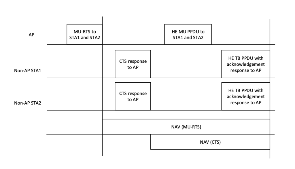
Figure1: (MU-OFDMA transmission with MU-RTS/CTS and Nav setting)
Before we start going through the MU-PPDU on Wireshark. It’s important to know there are different types of frame formats in 802.11ax standard.
- HE-SU: This is the transmission from a single station to another station.
- Sigle user mode (UL-DL)

- HE-EXT-SU: This PPDU is intended for long range transmission
- Single user mode (UL & DL)
- For outdoor use (long range)
- 20 MHz only BW, fixed modulation, and coding

- HE-MU: MU-PPDU is used for DL MU-OFDMA transmission. We will discuss this mode in this document.
- Multiuser mode (DL)
- One or more users
- HE-TRIG
- Trigger based PPDU (UL)
- In response to trigger from AP
- Carries single user transmission

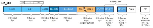
It’s also important to know that IEEE 802.11-2016 standard split preamble into 2 parts. One is legacy part which every frame has, and other part is PHY dependent.

(Figure2: 802.11 frame preamble)
Even though preamble info is important to know but some people might not be interested in reading that.
So, we will concentrate on only interesting part which is HE-SIGA & HE-SIGB information field which is related to MU OFDMA or MU-MIMO.
Thankfully Gjermundraaen have explained preamble in detail in his post.
https://gjermundsblog.files.wordpress.com/2019/07/dl-ofdma-he-mu-ppdu-bit-by-bit-2.pdf
L-STF, L-LTF and L-SIG are all legacy fields and are common in all PPDU format. RL-SIG (repeated legacy SIG) is to confirm what frame to expect whether its legacy OFDM, HT, VHT or HE.
(Figure3: MU-PPDU frame format)
In this post we will concentrate on only 2 fields.
- HE-SIG-A field
- HE-SIG-B field
HE-SIG-A field:
HE-SIG-A field carries information necessary to interpret HE PPDU’s. HE-SIG-A have different content depending on type of frame.
For example, HE SU PPDU, HE ER SU PPDU and HE MU PPDU’s will have different content in HE-SIG-A field. We will only concentrate on MU PPDU’s which is part of MU-OFDMA transmission.
HE-SIG-B field:
SIG-B field provides necessary information regarding OFDMA and DL MU-MIMO resource allocation.
This field only exists in multi-user transmission.
So, it is safe to say most of HE information data in the PCAP belongs to SIG-A.
Single-user transmission has only HE information field in the PPDU as show in in figure 7 below.

Figure4: (Single user PPDU)
We will try to identify both fields in a PCAP with help of Wireshark by expanding MU-PPDU.
Note: in a PCAP MU-PPDU there is no field called as SIG-A or SIG-B. instead we have HE information and HE-MU information which represents SIG-A and SIG-B values.
They could have arranged fields better or name it better in the PCAP so there is no confusion as in what field belongs to SIG-A or SIG-B.

(Figure5: MU-PPDU PCAP)
As we are exploring MU-PPDU so we will have both fields in the PCAP.
- HE information
- HE-MU information
HE information field is further divided into many subfields.
First 2 subfields HE data 1 and HE data 2 are just status information to shows whether some value is known or not known.
I will go through the fields, try to make sense of it and place in one of the category SIG-A or SIG-B.
HE information field:

(Figure5: HE fields)
Subfields from Data 3 to Data 6 and HE-MU information has information coming from SIG-A and SIG-B.

(Figure6: Data 3 to Data 6)
| Field value | HE information field | Description | Field |
| BSS color | Data 3 | Identified of BSS color | SIG-A |
| Beam change | Data 3 | Set to 1 to indicate that the pre-HE modulated fields of the PPDU may be spatially mapped differently from the first symbol of the HE-LTF. Set to 0 to indicate that the pre-HE modulated fields of the PPDU are spatially mapped the same way as the first symbol of the HE-LTF on each subcarrier. | SIG-A |
| UL/DL | Data 3 | Indicates is UL or DL 1 = towards AP (UL) 0 = towards STA (DL) | SIG-A |
| Data MCS | Data 3 | Indicates MCS value of SIG-B field | SIG-A |
| Data DCM | Data 3 | Indicates if SIG-B is modulated with DCM | SIG-A |
| Coding LDPC | Data 3 | ||
| LDPC extra | Data 3 | Indicates presence of LDPC extra symbol | SIG-A |
| STBC | Data 3 | All RU’s are STBC encoded = 1 All RU’s are not STBC encoded = 0 | SIG-A |
| Spatial reuse | Data 4 | Indicates whether spatial reuse is allowed. | SIG-A |
| STA-ID | Data 4 | STA-ID of | |
| Reserved | Data 4 | ||
| Data bandwidth/ RU allocation | Data 5 | Shows full bandwidth of the channel or RU allocated to this PPDU | |
| GI | Data 5 | Shows GI duration | SIG-A |
| LTF symbol size | Data 5 | GI GI duration LTF 0 4 0.8 μs 1 2 0.8 μs 2 2 1.6 μs 3 4 3.2 μs | SIG-A |
| LTF symbols | Data 5 | LTF symbol, Doppler and midable work together. Doppler LTF 0 0 1 2 2 4 3 6 4 8 | SIG-A |
| Reserved | Data 5 | ||
| Pre-FEC | Data 5 | Indicates the pre-FEC padding factor | |
| TxBF | Data 5 | ||
| PE | Data 5 | Indicated PE disambiguity | SIG-A |
| NSTS: space time stream | Data 6 | ||
| Doppler value | Data 6 | Doppler bit is used if packet length is larger then Mid-amble duration. The receiver can detect time-variation of channels based on the received packet and mid-ambles. | SIG-A |
| Reserved | Data 6 | SIG-A | |
| TXOP value | Data 6 | Set to 127 means no duration TXOP duration could be: 8 μs128 μs512 μs | SIG-A |
| Midamble | Data 6 | Midamble is used or not. To deal with channel under mobility, it is the process of adding HE-LTF between OFDMA symbols. | SIG-A |
(Tabe1: HE information PCAP)
HE-MU information:
HE-MU information which is only available in MU-PPDU. So most of this data represent SIG-B.

(Figure8: HE-MU information)
HE SIG-B content channel consist of a common field, if presents, followed by user specific field.
If the HE-SIG-B compression field in the SIG-A is 1 indicating full bandwidth MU-MIMO, then common field is not present.
But if you look at figure6 above flag2 SIG-B compression from SIG-A is false which means it’s not full bandwidth MU-MIMO and we do have common field in MU-PPDU.

HE-MU information structure:
- Flag1: Figure 8 above showing all Flag1 subfields are status fields.
- Flag2: some subfields are status, and some have some values which are shown in the table1 below.
- Channel 1 RU’s
- Channel 2 RU’s
Note: In a PCAP at the moment it’s not too clear what element belongs to SIG-B common field or user specific field.
It gets little confusing, because SIG-A & SIG-B elements are shown in HE information and HE-MU information together.
| Field Value | HE-MU information | Description | SIG-B | Field |
| Centre 26 tones RU | Flag1 | The Centre 26-tone RU field is present if the Bandwidth field in the HE-SIG-A field indicates a bandwidth greater than 40 MHz and not present otherwise. | Common | SIG-B |
| Bandwidth | Flag2 | N = 1 if the Bandwidth field in the HE-SIG-A field is 0 or 1 (indicating a 20 MHz or 40 MHz HE MU PPDU) N = 2 if the Bandwidth field in the HE-SIG-A field is 2, 4, or 5 (indicating an 80 MHz HE MU PPDU) N = 4 if the Bandwidth field in the HE-SIG-A field is 3, 6, or 7 (indicates a 160 MHz or 80+80 MHz HE MU PPDU) | common | SIG-B field coming from SIG-A |
| SIG-B compression | Flag 2 | If SIG-B compression from SIG-A is 1 then full bandwidth is being used. If 0 then its MU and common field should exist in the PPDU. | SIG-B coming from SIG-A | |
| SIG-B symbols | Flag2 | No of users in PPDU | common | SIG-B |
(Table2: MU-HE information field)
So let me try to put things together:
- if you look at figure8 above flag2 SIG-B compression from SIG-A is false which means it’s not full bandwidth MU-MIMO and we do have common field in MU-PPDU. It means we are using resource units
- MU-HE information showing N = 2 if the Bandwidth field in the HE-SIG-A field is 2, 4, or 5 (indicating an 80 MHz HE MU PPDU)
- SIG-B symbols flag2 shows 4 devices
- So, we have resource units on 80MHz and 4 devices
Channel 1 & Channel 2:
We can also see information regarding channel 1 and channel 2.
Channels show bit index of the RU allocation table.
Channel1 or channel2 known depends on channel bandwidth.
- Known field of channel 1 shows there was data captured on channel 1 and it’s used from 20MHz to onwards.
- Known field of channel 2 shows there was data capture on 40MHz or higher. It should be zero if it is only 20MHz.
| RU Index | bw=0 (20 MHz) | bw=1 (40 MHz) | bw=2 (80 MHz) | bw=3 (160 MHz) |
| RU[0] | -122:122 | -244:-3 | -500:-259 | -1012:-771 |
| RU[1] | / | / | 17:258 | -495:-254 |
| RU[2] | / | / | / | 12:253 |
| RU[3] | / | / | / | 529:770 |
| Center 26-tone | / | / | -16:-4, 4:16 | -528:-516, -508:-496 |
(Table3: channel 1)
| RU Index | bw=0 (20 MHz) | bw=1 (40 MHz) | bw=2 (80 MHz) | bw=3 (160 MHz) |
| RU[0] | / | 3:244 | -258:-17 | -770:529 |
| RU[1] | / | / | 259:500 | -253:-12 |
| RU[2] | / | / | / | 254:495 |
| RU[3] | / | / | / | 771:1012 |
| Center 26-tone | / | / | / | 496:508, 516:528 |
Table4: (channel 2)
Tables are taken from https://www.radiotap.org/fields/HE-MU.html
Let’s see in a PCAP how channel 1 and channel 2 is shown.

(Figure9: channel 1 and Channel 2 known)
In our PCAP above we had both channels known and channel1, Channel2 RU is also shown as bit index 192.
| RU Index | RU tones | RU tones | RU tones | RU tones | RU tones |
| 192 | 242 | 242 | 26 | 242 | 242 |
(Table3: RU allocation 80MHz)
It’s time to summarise full DL MU-OFDMA.
- SIG-B has the information regarding MU-OFDMA in MU-PPDU.
- We had 80MHz channel width
- Trigger frame sent from AP to multiple devices
- AP sent CTS after MU-trigger frame
- AP sent MU-PPDU to all clients
- HE-information field has shown 242 tones/RU for the frame (Figure 8)
- MU-HE information field is also showing bandwidth value as 2 in Flag2 which is more then 20 MHz which we know as 80MHz
- SIG-B compression is showing false which means it’s not a full bandwidth transmission.
- SIG-B symbol showing 4 clients
- Channel 1 and channel 2 showing bit index 192 which can be referred to RU allocation table. https://uk.mathworks.com/help/wlan/gs/he-mu-transmission.html

(Figure8: PPDU showing MU-OFDMA)
Pingback:802.11ax MU PPDU – Media Sat UK