My plan was to explain DL MU-OFDMA which includes trigger frames, CTS, MU-PPDU, and ACK in one post but that would become boring.
so I have decided to split it into 2 posts.
1- MU-Trigger frame
2- MU-PPDU
In this post, we will only look at MU-Trigger frame.
Note:
- PCAP is taken with help of raspberry Pi4 and intel AX210 card
- The scenario includes multiple clients and an 802.11ax hub
- Frame breakdown is done with the help of IEEE 802.11ax draft 2021
Let’s start:
MU-OFDMA transmission can start with an MU-Trigger frame and then CTS from each station or AP can send clear to send itself so no other device can transmit while AP is transmitting.
The figure below is taken from IEEE 802.11ax draft.
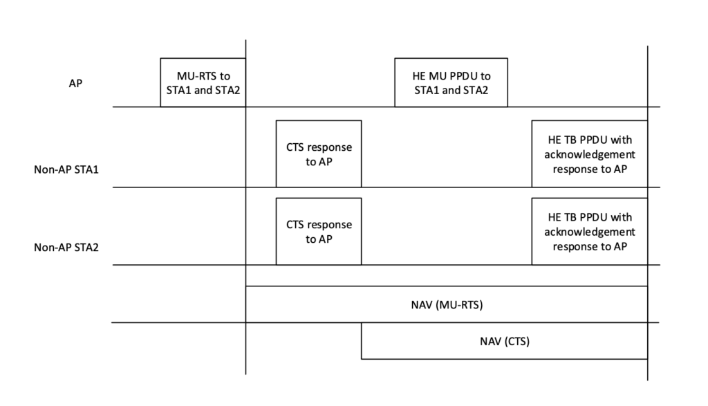
Figure:1 (MU-RTS/CTS) DL MU PPDU/ACK Response and Nav setting)
PCAP MU-OFDMA:
The capture below was taken with the help of Intel AX-210. I have omitted Mac address intentionally.
You can see that PCAP follows the same structure as the draft defines in the Figure1 above.
- MU-RTS trigger frame
- CTS response from devices mentioned in figure1. But we have CTS to self from the AP, so no other device transmits while AP is transmitting.
- Data: HE-MU PPDU which is 106-tones RU.
- ACK from devices once AP finished transmitting data. A HE non-AP STA responds with a HE TB PPDU if it receives either a Trigger frame or UMRS Control field.

(Figure:2 PCAP AX210)
Let’s investigate MU-Trigger frame:
There are multiple types of trigger frames, but we are looking at Trigger frame which is used for resource allocation to different users in MU-OFDMA transmission.
So, what to expect from MU-Trigger frame.


(Figure3: Trigger frame – PCAP AX210)
PCAP shows exactly same fields as frame format above taken from IEEE draft Figure9-64.
now let’s look at each field one by one.
- Frame control includes:
- Version control
- Frame type and subtype
- Flags is also part of frame control field which I have missed highlighting.
- Duration: Time it will take to transmit this frame
- RA/TA field: it’s a broadcast frame so receiver address will be always ff:ff:ff:ff:ff:ff and Transmitter address will be AP in this case.
- Common info: shows some AP configured info and for the clients to set up their UL traffic
- User info: RU related info specific to client device with their AID
- Padding and FCS are self-explanatory
In trigger frame mostly fields are arranged as legacy frames, but 2 information fields are new and need to look at them. These 2 fields are
- Common info
- User info

Now let’s look at the PCAP common field

(Figure4: Trigger frame common info field)
There is some interesting information available here. we will start from very first field and go through them one by one.
- We know it’s an MU-RTS trigger frame and it shows in common info as well.
- UL length subfield indicates the value of L-SIG LENGTH field of solicited HE TB PPDU.
- More TF indicates whether subsequent trigger fame is scheduled for transmission.
- CS: carrier sense required field is set to 1 to indicate that STAs identified in the user info fields are required to use ED (energy detect) to sense medium and consider the medium state and NAV in determining whether to respond.
- UL BW: Usually to describe UL bandwidth of response. But for MU-RTS UL BW subfield of the Common Info field indicates the bandwidth of the frame carrying MU-RTS.
| UL BW subfield value | Description |
| 0 | 20 MHz |
| 1 | 40 MHz |
| 2 | 80 MHz |
| 3 | 80+80 MHz or 160 MHz |
(Table1: UL BW encoding)
- The GI and HE-LTF indicate GI and HE-LTF type of the HE TB PPDU response.
| GI And HE-LTF Type subfield value | Description |
| 0 | 1x HE-LTF + 1.6 μs GI |
| 1 | 2x HE-LTF + 1.6 μs GI |
| 2 | 4x HE-LTF + 3.2 μs GI |
| 3 | Reserved |
(Table2: GI and He-LTF subfield encoding)
- The MU-MIMO HE-LTF Mode subfield of the Common Info field indicates the HE-LTF mode for an HE TB PPDU that has an RU that spans the entire bandwidth and that is assigned to more than one non-AP STA (i.e., for UL MU-MIMO).
- When GI & HE-LTF Type subfield of the Common Info field indicates either 2x HE-LTF + 1.6 μs GI or 4x HE-LTF + 3.2 μs GI in table2. Otherwise, this subfield is set to indicate HE single-stream pilot HE-LTF mode according to table3.
| MU-MIMO HE-LTF subfield value | Description |
| 0 | HE single-stream pilot HE-LTF mode |
| 1 | HE masked HE-LTF sequence mode |
(Table3: MU-MIMO HE-LTF mode encoding)
- The UL STBC subfield of the Common Info field indicates the status of STBC encoding for the solicited HE TB PPDUs. It is set to 1 to indicate STBC encoding and set to 0 otherwise.
- The LDPC Extra Symbol Segment subfield of the Common Info field indicates the status of the LDPC extra symbol segment. It is set to 1 if the LDPC extra symbol segment is present in the solicited HE TB PPDUs and set to 0 otherwise.
- The AP Tx Power subfield of the Common Info field indicates the AP’s combined transmit power at the transmit antenna connector of all the antennas used to transmit the triggering PPDU in units of dBm/20 MHz. The transmit power in dBm/20 MHz, PTX, is calculated as PTX = –20 + FVal, where FVal is the value of the AP Tx Power subfield, except for the values above 60, which are reserved.
- The Pre-FEC Padding Factor and PE Disambiguity subfields are defined in Table 9-29g and have the same encoding as their respective subfields in HE SIG-A
- The Doppler subfield of the Common Info field is set to 1 to indicate that a midamble is present in the HE TB PPDU and set to 0 otherwise.
- The UL HE-SIG-A2 Reserved subfield of the Common Info field carries the value to be included in the Reserved field in the HE-SIG-A2 subfield of the solicited HE TB PPDUs. HE AP sets the UL HE-SIG-A2 Reserved subfield to all 1s.
User Info:
User info as the name suggests this field shows information related to users. This should show what type of transmission AP is setting for client devices.

Now let’s expand user info:
In 20MHz it’s possible to have up to 9 RU’s which is 26 tones RU/device.

(Table4: 20MHz with a maximum of 9 users)
In our trigger frame in the example, we have only 2 devices.

(Figure5: user info field)
- AID is assigned to the device at the time of association response. AID subfield is encoded as below.
| AID12 subfield | Description |
| 0 | User Info field allocates one or more contiguous RA-RUs for associated STAs |
| 1–2007 | User Info field is addressed to an associated STA whose AID is equal to the value in the AID12 subfield |
| 2008–2044 | Reserved |
| 2045 | User Info field allocates one or more contiguous RA-RUs for unassociated STAs |
| 2046 | Unallocated RU |
| 2047–4094 | Reserved |
| 4095 | Start of Padding field |
- RU allocation work along with common info field UL bandwidth (UL BW) because RU allocation depends on the size of channel width. RU allocation region only useful when using 80+80 or 160MHz channel width.
- if the UL BW subfield indicates 20 MHz, 40 MHz, or 80 MHz PPDU, then B0 of the RU Allocation subfield is set to 0.
- If the UL BW subfield indicates 80+80 MHz or 160 MHz, then B0 of the RU Allocation subfield is set to 0 to indicate that the RU allocation applies to the primary 80 MHz
- If the UL BW subfield indicates 80+80 MHz or 160 MHz, and BO of RU allocation subfield is set to 1 to indicate that RU allocation applies to secondary 80MHz channel.
- Next field RU allocation (tones) shows how many tones/RU is assigned to this device or STA for DL traffic.
| B7–B1 of the RU Allocation subfield | UL BW subfield | RU size | RU Index |
| 0–8 | 20 MHz, 40 MHz, 80 MHz, 80+80 MHz or 160 MHz | 26 | RU1 to RU9, respectively |
| 9–17 | 40 MHz, 80 MHz, 80+80 MHz or 160 MHz | RU10 to RU18, respectively | |
| 18–36 | 80 MHz, 80+80 MHz or 160 MHz | RU19 to RU37, respectively | |
| 37–40 | 20 MHz, 40 MHz, 80 MHz, 80+80 MHz or 160 MHz | 52 | RU1 to RU4, respectively |
| 41–44 | 40 MHz, 80 MHz, 80+80 MHz or 160 MHz | RU5 to RU8, respectively | |
| 45–52 | 80 MHz, 80+80 MHz or 160 MHz | RU9 to RU16, respectively | |
| 53, 54 | 20 MHz, 40 MHz, 80 MHz, 80+80 MHz or 160 MHz | 106 | RU1 and RU2, respectively |
| 55, 56 | 40 MHz, 80 MHz, 80+80 MHz or 160 MHz | RU3 and RU4, respectively | |
| 57–60 | 80 MHz, 80+80 MHz or 160 MHz | RU5 to RU8, respectively | |
| 61 | 20 MHz, 40 MHz, 80 MHz, 80+80 MHz or 160 MHz | 242 | RU1 |
| 62 | 40 MHz, 80 MHz, 80+80 MHz or 160 MHz | RU2 | |
| 63, 64 | 80 MHz, 80+80 MHz or 160 MHz | RU3 and RU4, respectively | |
| 65 | 40 MHz, 80 MHz, 80+80 MHz or 160 MHz | 484 | RU1 |
| 66 | 80 MHz, 80+80 MHz or 160 MHz | RU2 | |
| 67 | 80 MHz, 80+80 MHz or 160 MHz | 996 | RU1 |
| 68 | 80+80 MHz or 160 MHz | 2×996 | RU1 |
| NOTE—If the UL BW subfield indicates 80+80 MHz or 160 MHz, the description indicates the RU index for the primary 80 MHz channel or secondary 80 MHz channel as indicated by B0 of the RU Allocation subfield. | |||
- The UL FEC Coding Type subfield of the User Info field indicates the code type of the solicited HE TB PPDU. The UL FEC Coding Type subfield is set to 0 to indicate BCC and set to 1 to indicate LDPC.
- The UL HE-MCS subfield of the User Info field indicates the HE-MCS of the solicited HE TB PPDU.
- The UL DCM subfield of the User Info field indicates DCM of the solicited HE TB PPDU. The UL DCM subfield is set to 1 to indicate that DCM is used in the solicited HE TB PPDU. The UL DCM subfield is set to 0 to indicate that DCM is not used. The UL DCM subfield is set to 0 if the UL STBC subfield of the Common Info field is set to 1.
- The SS Allocation subfield of the User Info field indicates the spatial streams of the solicited HE TB PPDU and the format
- The UL Target Receive Power subfield indicates the expected receive signal power, measured at the AP’s antenna connector and averaged over the antennas, for the HE portion of the HE TB PPDU transmitted on the assigned RU and is defined in Table below.
| UL Target Receive Power subfield | Description |
| 0–90 | The expected receive signal power, in units of dBm, is Targetpwr = –110 + Fval, where Fval is the subfield value |
| 91–126 | Reserved |
| 127 | The STA transmits the HE TB PPDU at the STA’s maximum transmit power for the assigned HE-MCS.The expected receive signal power is then the STA’s maximum transmit power for the assigned HE-MCS minus the path loss. |
Pingback:802.11ax MU PPDU - WiFi
All Figures in this blog are missing. Would really help if the issue is fixed.
I am able to see the figures. Is anyone else having the same issue
Can’t see figures.
Sorry guys..
looks like an update on WordPress messed up figures on this post. I will check the rest as well.
I have uploaded the figures again…
Do you have a guide on how to setup a PC with AX210 to capture OFDMA frames? Any special settings need to be used?
I came across your site wanting to learn more and you did not disappoint. Keep up the terrific work, and just so you know, I have bookmarked your page to stay in the loop of your future posts. Here is mine at FQ5 about Airport Transfer. Have a wonderful day!
This was a very good post. Check out my web page 63U for additional views concerning about Thai-Massage.
This was a very good post. Check out my web page QU6 for additional views concerning about Thai-Massage.
Hello, I apprecitate the blog writeup on such a confusing topic, and the efforts put in to present the content well.
Yet, I find the blog super confusing and wrong in the figures, I am a new learner to 11ax, and then needed to use ChatGPT – I finally after reading multiple times, and brainstorming a lot of time combined with Chatgpt support, was able to understand where the gaps exist –
1. the timeline diagram 1 shows MU-RTS and CTS, but does NOT show the pure MU OFDMA trigger frame that synchronizes following UL transmissions from STAs. but these are shown and the pure MU OFDMA trigger frame is ENTIRELY MISSING. i was confused that the MU-RTS is itself the trigger frame/ is it embedded in DL PPDU? No, it is MISSING
2, the 2nd frame format diagram depicts and talks about pure MU OFDMA trigger frame that synchronizes following UL transmissions from STAs –
the immeidate jump of context without explicit mention, combined with wrong figure 1 ( wrong due to missing pure MU OFDMA trigger frame ) causes lot of confusion/erratic understanding.
PLEASE FIX THESE TWO ASPECTS IMMEDIATELY to help learners like me.
Ravi K